ATA/IDE/EIDE/SATA
 Early PCs using the IDE interface had ISA expansion boards with an IDE connector. Most motherboards available today have multiple integrated IDE connectors. The first IDE devices were rather slow, using the 8-bit ISA interface the maximum data throughput was 4MBps, 16-bit IDE connections allowed up to 8 MBps. This first IDE/ATA standard has support for only one channel allowing a maximum of two hard disks. It supports PIO modes 0, 1, and 2, and single word DMA modes 0, 1, and 2, and multiword DMA mode 0.
PIO modes and DMA modes define different methods for the disk drive to communicate with the system. The older method Programmed I/O (PIO) requires the help of the CPU to transfer data between the disk and the system's memory. There are 5 different PIO modes listed in the following table along with their corresponding maximum transfer rates:
| PIO Mode | Transfer Rate (MBps) |
| Mode 0 |
3.3
|
| Mode 1 | 5.2 |
| Mode 2 | 8.3 |
| Mode 3 | 11.1 |
| Mode 4 | 16.7 |
DMA is short for Direct Memory Access. As it name implies, DMA allow direct access to the system's memory, bypassing the CPU. Single word DMA transfers a single word (2 bytes/16-bits) per transfer session, where multiword DMA sets up a transfer session and sends several words after each other, reducing the overhead per transfer session. The following table lists the different DMA modes along with their corresponding maximum transfer rates:
| DMA Mode | Transfer Rate (MBps) |
| Single word 0 |
2.1
|
| Single word 1 | 4.2 |
| Single word 2 | 8.3 |
| Multiword 0 | 4.2 |
| Multiword 1 | 13.3 |
| Multiword 2 | 16.7 |
In 1994 Enhanced IDE (EIDE) was developed by Western Digital to:
- increase the maximum data throughput to up to 16.7 MBps.
- increase the 528MB size limit to 8.4GB.
- support two controllers instead of one, allowing a maximum of four disks instead of two.
Seagate and Quantum developed similar technologies which were promoted as FASTATA and FASTATA-2. Eventually, the features of the these unofficial standards were combined in the official standard ATA-2. Besides the improvements listed above, ATA-2 offers support for:
- Logical Block Addressing (LBA) and block transfer
- PIO modes 3 and 4
- Multiword DMA modes 1 and 2
Several CD-ROM drive manufacturers, including Western Digital, worked together to develop a specification that would allow CD-ROM drives and tape drives to be connected to the same interface and cable as hard disk drives. The Small Form Factor (SFF) committee initially published it as the AT Attachment Packet Interface (ATAPI) specification. ATAPI eventually became an extension to ATA in ATA/ATAPI-4.
Several other additions were made to the ATA standard, such as ATA-3, which introduced some reliability features and allowed password protection for devices. The first major new version of ATA was ATA/ATAPI-4, which combined ATA with ATAPI and introduced Ultra DMA. Again there are several modes, all multiword, of Ultra DMA. The table below lists the Ultra DMA modes along with their corresponding maximum transfer rates. ATA/ATAPI 4 supports Ultra DMA mode 0, 1, and 2. Ultra DMA mode 2 is also known as Ultra DMA/33, Ultra-ATA, and ATA-33.
Several other additions were made to the ATA standard, such as ATA-3, which introduced some reliability features and allowed password protection for devices. The first major new version of ATA was ATA/ATAPI-4, which combined ATA with ATAPI and introduced Ultra DMA. Again there are several modes, all multiword, of Ultra DMA. The table below lists the Ultra DMA modes along with their corresponding maximum transfer rates. ATA/ATAPI 4 supports Ultra DMA mode 0, 1, and 2. Ultra DMA mode 2 is also known as Ultra DMA/33, Ultra-ATA, and ATA-33.
| Ultra DMA Mode | Transfer Rate (MBps) |
| Mode 0 |
16.7
|
| Mode 1 | 25 |
| Mode 2 | 33.3 |
| Mode 3 | 44.4 |
| Mode 4 | 66.7 |
| Mode 5 | 100 |
| Mode 6 | 133 |
ATA/ATAPI-5, added support for Ultra DMA mode 3 and 4. Ultra DMA mode 4 is also known as Ultra DMA/66. ATA/ATAPI-6 introduced Ultra DMA mode 5, supporting data transfer rates up to 100MBps.
Intel and a group of other companies have developed a serial version as an alternative to the parallel ATA interface and was published as Serial ATA (SATA). The SATA specification was handed over to T13 to include it in ATA/ATAPI-7 (volume 3) and is now called SATA-1. ATA/ATAPI-7 includes UltraDMA mode 6 already known as Ultra DMA 133, some new commands for use by digital video recorders, and T13's version of Serial ATA, SATA-1. SATA can transfer data up to 150MBps (and will likely advance to 300 MB and 600 MB per second in the near future), making it, in theory, faster than parallel ATA (now also referred to as PATA) using UltraDMA mode 6 running at 133MBps. These transfer rates are so called burst rates, the average rates are much lower making the difference between PATA and SATA very small. The currently available SATA hard disk are mostly not native SATA drives, instead the disks include a chip that functions as a parallel-to-serial bridge. This bridge limits the transfer rates which would be 1.5Gbps according to the first version of SATA.
The Serial ATA final 1.0a specification was released on Feb 4, 2003. Intel continues to work on SATA and joined forces with a the Serial Attached SCSI (SAS) subdivision of T10. They are currently working on an extension to the SATA 1.0a specification, called SATA II, which focuses on support for multiple devices per SATA bus, RAID, and more.
Installing an 'IDE' device
A standard PC is usually equipped with two IDE controllers ("ATA interfaces"  ), a primary and a secondary controller, also referred to as the primary and the secondary IDE channel. Per channel you can connect two devices, hence a standard PC can hold up to four IDE devices in total. The following picture shows the primary and the secondary IDE connector on the mainboard.

When two devices are connected to a single IDE channel, using the same physical cable, one device must be configured as master and the other as slave. This is usually done by setting a jumper on the device. Two other settings that typically can be set by the jumper are Cable Select (the master/slave setting will be based on the position of the device on the cable. The device farthest from the IDE controller will be selected as master) and Single (this setting can be used when there is only one device connected to the cable.)
When two devices are connected to a single IDE channel, using the same physical cable, one device must be configured as master and the other as slave. This is usually done by setting a jumper on the device. Two other settings that typically can be set by the jumper are Cable Select (the master/slave setting will be based on the position of the device on the cable. The device farthest from the IDE controller will be selected as master) and Single (this setting can be used when there is only one device connected to the cable.)
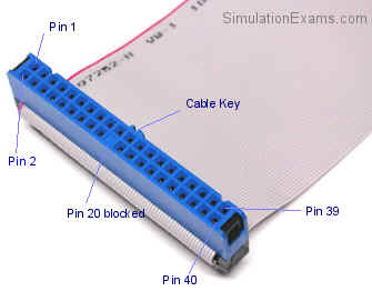
The picture below on the left, shows a regular flat ribbon 40-pins/wires IDE cable with 3 connectors, also referred to as an IDE-33 cable. The devices connect to the two connector closest together, the connector on the far end connects to the mainboard's IDE connector. One side of the cable has a red edge to mark the side that connects to pin 1 on the mainboard's connector and pin 1 on the device.
 |  |
The picture on the right shows a flat ribbon IDE-66/100 cable with 80 wires. The extra 40 strands in an 80-wire cable act as insulators between the 40 signaling strands to prevent crosstalk. This type of cable usually has one blue connector, this connector connects to one of the mainboard's IDE connectors. The black connector connect to the master device and the gray/white connector to the slave. This type of cable was optional for ATA/ATAPI-4 compliant devices and is mandatory in ATA/ATAPI-5 to be able to support the maximum transfer rates. If you have an ATA/66, 100 or 133 drive without the 80-wire cable, the drive will only run at 33MB/sec. An alternative to the flat ribbon cable has been introduced a couple of years ago. The main advantage is better airflow inside the computer's case, hence a 'cooler' system.
SATA supports a single device per SATA cable. A SATA cable can be longer than a parallel ATA cable (max. 1.5 feet), about 3 feet. Serial ATA has a thinner cable and a smaller connection that is keyed so they cannot be connected incorrectly, unlike some parallel ATA cables. The following pictures show the new Serial ATA 7-wires cable and its connectors.
SATA supports a single device per SATA cable. A SATA cable can be longer than a parallel ATA cable (max. 1.5 feet), about 3 feet. Serial ATA has a thinner cable and a smaller connection that is keyed so they cannot be connected incorrectly, unlike some parallel ATA cables. The following pictures show the new Serial ATA 7-wires cable and its connectors.
 |  |
RAID
RAID stand for Redundant Array of Inexpensive (or Independent) Disks, and is commonly used on servers in corporate environments. It allows multiple hard disks to be combined. The three most common, and important for the Network+ exam, are described next.
RAID 1 refers to Disk Mirroring/Duplexing. This configuration requires two, in some cases identical, hard disks. When the OS writes data to the hard disk, the same data is also written to the mirrored disk. This may slow down write performance, but increases read performance since data can be read form both disks at the same time. It's called duplexing when each disk has its own hard disk controller, providing an extra level of redundancy. When a disk fails the other disk can continue to operate, in some configurations this process occurs entirely automatically. In Window NT and higher, when the main disk fails, you'll need to manually configure the system to use the mirrored disk.
RAID 5 is more advanced and requires at least 3 hard disks. RAID 5 is also known as a stripe set with parity. When data is written to the RAID 5 set, it is distributed over several disks, and parity information about data blocks on one disk are stored on the other disks. In case of a disk failure, the parity information can be used to reconstruct the data which was on the missing disk. Because data is spread out over several disks, RAID 5 offers better read performance than single or mirrored disks. But because every write requires the parity calculation, write performance can be slower, especially when RAID 5 is implemented in software. If two disks in a RAID 5 set fail, you will need to replace the disks and restore the information from backup.
Fault tolerance RAID configurations implemented in hardware usually offer hot-swapable drives. This means you can pull out and replace a drive while the system is running, and it will perform the reconstruction of the data automatically.
Another type is RAID 0, also known as a stripe set. It requires at least 2 hard disks, but does not offer fault tolerance, it's merely a method of combining hard disks to allow for larger volumes. When a file is written to a RAID 0 stripe set with 2 disks, the first block is written to the first disk, the second block to the second disk, and the third data block is written on the first disk, and so on. If one of the hard disks in the stripe set fails, the entire stripe set is lost and needs to be rebuild and restored from backup.
No comments:
Post a Comment