Circuit switching vs. Packet switching
Circuit switching and packet switching are both communication methods for large networks. The most common example of a circuit switching network is the telephone system: the sender and the receiver establish a dedicated physical path for the entire duration of the call. All of the transmitted information follows the same route and the circuit is available only to the nodes that established it. PSTN (Public Switched Telephone Network), covered in the Internet Connections TechNotes, and ISDN, covered below, both use the circuit switching technology.
In packet switching networks, data is segmented into packets that each take a route independently based on the addressing information their header. In theory, the route can be different for each packet, but also one and the same. The packet is sent from hop to hop whereby each hop (e.g. a router) determines the best next part of the route. Other nodes can send packets, seemingly simultaneously, over the same dynamic route. Most large WANs are largely made up of packet switching networks, the Internet being the most common example.
ISDN
Integrated Services Digital Network (ISDN) is a circuit-switching network used for voice, data, and video transfer over plain copper telephone lines. ISDN is a bit similar to the normal telephone system but it is faster, more reliable, and requires less time to setup a call. Digital ISDN phones digital faxes are usually provided by the telco. An ISDN modem can be used to convert the signals of non-ISDN equipment to ISDN signals. An ISDN modem can be external or internal and is usually connected to the wall outlet by using an UTP cable with an 8-pin RJ-45 connector on the modem side, and a 6-pin RJ-11 connector on wall jack side. Some ISDN modems use or allow in addition an RJ-45 to RJ45 or RJ-11 to RJ-11 connection. An ISDN modem can also be integrated in a router to provide a shared WAN or Internet connection for multiple users in a network.
An ISDN connection consists of several different types of digital channel. The 64 Kb B-channel used for transferring data, and the D-channel used for transmitting control information are the most common type of channels in use. Most home users or smaller organizations with an ISDN connection usually have an ISDN BRI(Basic-Rate Interface) connection. Two B-channels + one D-channel make up ISDN BRI. Some remote access servers support a feature called multilink allowing the two B-channels to be combined in a single virtual link of 128 Kbps. In reality, often 1 B-channel is used for data (an Internet connection for example) and 1 B-channel is used for voice (connected to a digital telephone for example).
ISDN PRI (Primary-Rate Interface) is more often used by medium to large sized organizations and is made up of 23 B-channels and 1 D-channel. The European version of PRI supports 30 B-channels. A common implementation of these two types of ISDN is a remote access solution with ISDN PRI at the corporate network supporting 23 dial-in connections for employees with ISDN BRI at home.
T1/E1/J1 & T3/E3/J3
A T1 connection is a digital leased line made up of 24 channels (called DS0, 1 DS0 is 64K) that providing transfer rates up to 1.544 Mbps, and is often used to connect corporate networks and ISPs to the Internet. The European version E1 is made up of 30 channels providing rates up to 2.048 Mbps. The Japanese version is made up of 24 channels just like a T1. They all use the DS1 signaling standard and that's why a T1 connections is sometimes also referred to as a DS1 line.
A T3 is an even faster digital leased line providing rates up to 44.736 Mbps (672 channels), and is used for high-speed Internet backbones and large organizations. The European version E3 provides rates up to 34.368 Mbit/s (512 channels ) The Japanese version J3 provides rates up to 34.064 Mbps (480 channels). T3, E3, and J3 use the DS3 signaling standard.
A CSU/DSU (Channel Service Unit/Data Service Unit) is a modem-like device that converts digital data frames from the communications technology used on a LAN into frames appropriate to a WAN and vice versa. This device sits on both ends of the T1/T3 connection, sometimes as an integrated device in a router.
SONET/OCx
Sonet(Synchronous Optical NETwork) is a hierarchy of standardized digital data rates for optical transmission interfaces proposed by Bellcore. The data rates in these fiber optic networks are divided in OC-levels. The following table lists the speeds for all OC levels:
OC-1 = 51.85 Mbps
OC-3 = 155.52 Mbps
OC-9 = 466.56 Mbps
OC-12 = 622.08 Mbps
OC-18 = 933.12 Mbps
OC-24 = 1.244 Gbps
OC-36 = 1.866 Gbps
OC-48 = 2.488 Gbps
OC-192 = 9.952 GbpsOC-768 = 40 GbpsOC-3072 = 160 Gbps
Obviously, you only need to remember the speed of OC-1, for example: OC-192 is simply 192 times the speed of OC-1.
X.25
X.25 is a classic packet-switching standard from ITU-T that operates at the Physical, Data Link, and Network layers of the OSI model. It uses PSTN and ISDN connections to allow large scale WANs. X.25 was mainly used in older environments with remote terminals connected through a simple PSTN modem connection. Because the older telephone lines were prone to error and interference, X.25 is mainly concerned with error-correction to allow a more reliable connection. The main part of an X.25 network usually belongs to a public carrier, and subscribers connected to it usually pay for the bandwidth they use.
(The following two WAN technologies are no longer on the Network+ exam but are still part of these TechNotes because they cover current network technologies that are actually newer than X.25.)
ATM
ATM is short for Asynchronous Transfer Mode, a packet-switching network that is commonly used for high-speed backbones in large network environments such as the Internet, for voice, data and video transfer. Data is transmitted in small 53-byte fixed length cells , and that is why ATM is also referred to as a cell-switching network . Partly because of the fixed length cell approach, ATM is able to reach data rates up to 622 Mbps. Also, an ATM switch uses integrated hardware circuits that switch cells between incoming and outgoing ports which significantly increase data throughput compared to software based switching. Every cell with the same source and destination address travels over the same route if possible.
ATM supports several innovative features such as Bandwidth on demand and QoS (Quality of Service). The latter allows data to be prioritized based on the content. For example, real-time video transfer could have a higher priority than file transfer, to allow the user to watch the video without interruptions. ATM uses its own reference model, which corresponds roughly to both the OSI Data Link and the Physical Layer. ATM supports different types of physical media including, OC-3, OC-12, TE/E3, UTP and FDDI.
Frame Relay
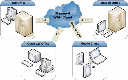
Frame Relay, one of today's most common examples of a packet-switching network, is a high-performance WAN protocol that operates at the physical and data link layers of the OSI model. An advantage of using Frame Relay is that the physical network medium and the available bandwidth are dynamically shared between the connected end nodes. Common use of Frame Relay is to interconnect LANs in a WAN and provide centralized shared Internet connectivity to remote offices. Frame Relay can be very cost-effective because generally you often only pay for the bandwidth usage. A Frame Relay network is represented as a cloud like in the following network diagram:

The cloud typically represents the carrier’s network, which can be a public network owned by the phone company or a private Frame Relay network. Multiple parties, such as different companies, can share the same Frame Relay network. To ensure there is bandwidth available, the carrier and the customer agree on a Committed Information Rate (CIR) . This is where you pay for; if more bandwidth is available you'll be able to use it but the CIR is the minimum guaranteed bandwidth available. Common line speeds in the US are fractional T1 to T1 (1.544 Mbps). Frame Relay supports a wide variety of physical media including ISDN and T1.
The boxes in the diagram above represent the routers (which can also be terminals, PCs, bridges etc.) are located on the premises of a customer. The connections between two locations are called Virtual Circuits; there are two types of VCs in frame relay:
- Permanent Virtual Circuits: manually configured permanent connection.- Switched Virtual Circuits: dynamic connection, created when needed.
- Permanent Virtual Circuits: manually configured permanent connection.- Switched Virtual Circuits: dynamic connection, created when needed.
No comments:
Post a Comment